UNITED STATES PATENT OFFICE
FRANK R. CUNNINGHAM, OF MEDFORD, MASSACHUSETTS, ASSIGNOR TO KENDRICK & DAVIS,
OF LEBANON, NEW HAMPSHIRE, A FIRM.
STAKING-TOOL.
No. 904,847. Specification of Letters Patent. Patented November 24, 1908.
Application filed October 23, 1907. Serial No. 398,758.
FRANK R. CUNNINGHAM, OF MEDFORD, MASSACHUSETTS, ASSIGNOR TO KENDRICK & DAVIS,
OF LEBANON, NEW HAMPSHIRE, A FIRM.
STAKING-TOOL.
No. 904,847. Specification of Letters Patent. Patented November 24, 1908.
Application filed October 23, 1907. Serial No. 398,758.
To all whom it may concern:
Be it known that I, Frank R. Cunningham, of Medford, in the county of Middlesex and State of Massachusetts, have invented certain new and useful Improvements in Staking-Tools, of which the following is a specification.
This invention relates to tools by which pinions and the staffs of balance-wheels and the hands of watches may be staked on, and by which the bearing recesses for the pinion pivots in the plates of watches and clocks and in the main-spring drums may be reduced in size.
The principal object of the invention is to increase the capacity and range of work of such, a tool by enabling each of the punches which are supplied with the tool, to be used as a stump.
Other objects are to enable watch hands to be staked on without requiring the tool to be elevated on a block, and to provide an improved locking means for securing the die in position.
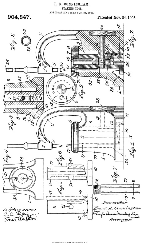
Of the accompanying drawings,—Figure 1 represents an elevation of a staking tool designed to secure the objects above named. Fig. 2 represents a similar view, showing the base of the tool in section. Fig. 3 represents a cross-section of the base on line 3—3 of Fig. 1. Fig. 4 represents a rear elevation of the base of the tool. Figs. 5 and 6 represent elevations at right angles to each other, of the detachable core which is contained within the base. Fig. 7 represents an elevation of a sleeve for holding a punch when used as a stump. Fig. 8 represents a section of the sleeve on line 8—8 of Fig. 1. Fig. 9 represents a plan view of the die.
The same reference characters indicate the same parts in all the figures.
The tool consists of a base 1 from one side of which rises a neck 2 which curves over and overlies the base, and terminates in a sleeve 3 at one side of the axis of the base. This sleeve serves as usual, as a guide for the punch 4, and for a centering tool 5. On the top of the base is pivotally mounted a circular die 6 having a circular series of holes which are adapted to be brought in turn beneath the punch guide and in line with the axis thereof by rotation of the die. The die 6 is not pivoted directly to the base 1 of the tool but is mounted upon a pivot pin 7, which passes loosely into a core 8 contained in a cavity 9 in the base. This cavity is vertical and cylindrical, being approximately coaxial with the base, and the core 8 is also mainly cylindrical, and is located coaxially of the base by means of a flange 10 surrounding its lower end and entering a cup-shaped groove 11 surrounding the lower end of the cavity 9. This groove joins the cavity at a shoulder 12 which serves as a bearing for the upper surface of the flange 10 to cause clamping of the die against the top of the base, the flange 10 and shoulder 12 constituting cooperating gripping abutments, as will be presently described. As the core is of considerably less diameter than the cavity 9, an annular space surrounding the core is provided. The series of holes in the die coincides with and overlies this space.
As will be seen from Fig. 9, the holes in the die vary greatly so as to serve the various purposes for which the tool is designed. One of the largest holes, represented by 13, is provided to receive the shanks of the stumps, of which several are furnished with each tool. A still larger hole 14 is provided so as to receive the bodies of the punches. When a punch is placed in the hole 14, its body extends into the annular portion of the cavity 9 and bears at its bottom against the flange 10. This causes all but its tapered end to lie within the base.
As will be seen in Figs. 5 and 6, the lower end of the core 8 is partially surrounded by helical cam surfaces 15 and 16. These surfaces merge with the top of the flange 10 at the front of the core and rise upwardly at each side. Thus when the punch 17 is directly below the punch 4, it rests on the flange and is retracted to its greatest extent, but when the die is turned, the end of the punch rides up on one of the helical cam surfaces and its outer end is further projected, allowing it to be grasped and withdrawn.
The die turns freely on the die bolt 7, being retained by the head 18 of the latter, and rests against the top surface of the base. The core 8 is somewhat shorter than the base, so there is no engagement between its upper end and the die. The core and die bolt are perforated, as is also the rear portion of the base, to permit a shaft 19, for locking the die in place, to pass through. The perforations 21 21 of the core are in line with each other and are circular to serve as bearings for the shaft. The perforation 22 in the die bolt receives a reduced eccentric crank-pin or cam 23 formed on the shaft 19, and is wide enough so as not to interfere with the rotation of the cam. A screw abutment 24 is threaded into the lower end of the die bolt, entering the slot 22 and lying where it can be engaged by the pin 23 when the latter is at its lowest point. Preferably the passage in the base through which the shaft 19 extends is enough larger than the shaft so that there may be no bearing, and the core 8 will be left free to adjust itself in the base. Whenever the shaft 19 is turned so as to bear against the abutment 24, it draws the die 6 down upon the top of the base 1, at the same time pressing the flange 10 of the core upward against the shoulder 12, thus gripping the base between the shoulder and die and effectually clamping and locking the latter in place. A pin 25 is pressed by a spring 26 into a groove in the side of the shaft 19. This spring bears against a removable screw abutment 27 and causes the pin to press with some force against the shaft. The friction caused thereby holds the shaft so that it will not be dislodged by jarring of the tool from any position in which it may be lodged when relieved from the abutment 24. Except upon removal of the abutment 27 and spring, the shaft 19 cannot be displaced.
For turning the shaft, I provide a knurled wheel 28 set into a socket in the rear face of the base. On the rim of this wheel are index marks 29 and 30 which cooperate with a fixed mark 31 on the base to indicate the proper adjustment for the screw abutment 24. This screw can easily be reached and turned by a screw-driver inserted in the central cavity of the core from the bottom of the staking tool. The adjustment is made so that the eccentric will crowd the die hard against the top of the base before arriving in quite its lowest position. That is, the die is held tight against the base while the center of the eccentric is still somewhat to one side of the axis of the abutment screw. This gives sufficient scope for some wear without so loosening the parts as to make them fail to grip tightly. When either of the marks 29 or 30 is in line with the mark 31, the die should be firmly clamped, and the eccentric so near the center line as to be held by friction beyond possibility of jarring loose when the tool is pounded upon, so the marks are used for reference in adjusting the abutment screw 24. The adjustment is complete when the parts are so tight that the wheel 28 cannot be turned beyond the mark 29 in right-hand rotation, or 30 when turned to the left. The two marks and the arrows are provided for the convenience of the workman, some preferring to turn the disk to the right and others to the left when tightening the die.
It will be noted that in the hole 14 which receives the punches 17, is screwed a split sleeve 32 from which the separated arms 33 extend into the annular space. These arms are segments of a cylinder and are convex externally and concave internally, their interior radius being equal to that of the hole 14 and the punch. These arms are springy and grasp the body of the punch, holding it in line with the punch 4 and allowing it to ride up the incline 15 or 16 without binding in the hole 14 as the die is turned. This tool differs from the staking tools hitherto made, among other things, in having the base of sufficient height to receive almost the entire length of the punches when used as stumps. The increased height of the base has another object also, that of permitting a watch movement to be held upon a stump while the hands are staked on. In staking on the hands, the hand arbor must be supported by. a stump, and to permit this the covers of the case must be opened. With the previously made staking-tools, the base is too short to allow the watch to be so held, but with the present form of machine, the watch cover when opened and the watch is placed on top of the die, will not extend as far as the bottom of the base. Another advantage arising from the increased height of the base is that the workman is enabled to hold the work in a natural manner. The base is approximately as high as the width of a man’s hand. Consequently, a piece of work may be held extending over the die, while the workman rests his closed hand on the bench beside the tool and holds the work between his thumb and fore-finger. With the old style of tool, it is necessary to rest the hands at some distance from the tool and incline the thumbs inward. In this position the work cannot be easily held.
Staking tools are ordinarily sold with a number of stumps and a greater number of punches. Many of these punches are longitudinally perforated in their ends in the same manner as are the stumps, and furthermore are reduced to smaller diameters at their ends so as to be capable of entering smaller recesses. They also are of different sizes from the stumps. By adapting the machine to employ punches as stumps, some hitherto impossible classes of work can be performed, while the range and variety of the work is greatly increased.
In order to position the anvil, the centering tool is passed through the guide sleeve 3. This has a tapered point 34 adapted to enter any one of the holes of the die and locate the center thereof directly in the axis of the guide. When a solid punch is inserted in the hole 14, it is centered by a conical socket 35 in the other end of the tool. This socket takes over the tapered end of the punch, and locates it exactly in the proper line. Staffs and jewels which are punched out of the work fall through the space 9 and are removed through a passage 36 in the base.
I claim:—
1. A staking tool comprising a base, a die mounted thereon, and an overhanging head having a passageway for an operating tool, said base having provisions for holding a punch so that the same may be used as a die or anvil and for sustaining the end thrust received by the punch when so used.
2. A staking tool including a perforated die, of which one of the perforations is adapted to receive a punch, having a base portion of a height commensurate with the length of a standard punch, whereby substantially the whole of the punch may be contained below the top of the die, and an abutment within the circumference of the base for supporting the punch.
3. A staking tool comprising a base, a rotary die mounted rotarily thereon and having perforations, one of which is capable of containing a punch, said base including an annular space to receive the stem of the punch, and a cam surface for forcing the punch upward as the die is turned.
4. A staking tool including a die having a plurality of sockets of various sizes, one of said sockets being of a size to receive a series of stumps, and one of them, also, being adapted to receive each of the punches associated with the tool and to hold such punch with its operative end in position to serve as a stump, whereby the capacity and range of work performed by the tool may be largely increased, and provisions for supporting a punch within the base when so used.
5. A staking tool comprising a base, an overhanging punch guide, a die rotatably mounted on said base and having a series of passages through it adapted to be brought into the axial line of said guide, one of said passages being of a size sufficient to receive a punch, and resilient members extending from said die and forming continuations of the walls of the last-named passage, to embrace the punch over a considerable proportion of its extent.
6. A staking tool comprising a base, an overhanging punch guide, a die rotatably mounted on said base and having a series of holes adapted to be brought into the axial line of said guide, one of said holes being of a size sufficient to receive a punch, and the base having a cavity for containing the body of the punch, and a cam within said cavity having surfaces extending upward from front to rear, whereby the punch is projected from the die as the latter is rotated to carry the punch away from the guide.
7. A staking tool comprising a base having a cavity, a core contained within said cavity and separated from the walls thereof by an annular space, a perforated die pivoted on said core, covering said annular space and being adapted to hold a punch in one of its perforations with the shank thereof extending into the space, and an inclined cam surface on the base of said core arranged to be engaged by the end of the punch in the rotation of the die.
8. A staking tool comprising a base having a cavity, a core contained within said cavity and having a flange on its base separating its periphery from the walls of the cavity by an annular space, and a die pivoted to the top of said core and overlying said space, said die having a perforation adapted to receive a punch and permit the shank thereof to pass through said space and bear on the flange of the core, said core having also a cam surface rising upward from the flange to cause projection of the punch as the die is rotated.
9. A staking tool comprising a base having a cavity, a core contained within said cavity and having a flange on its base separating its periphery from the walls of the cavity by an annular space, and a die pivoted to the top of said core and overlying said space, said die having a perforation adapted to receive a punch and permit the shank thereof to pass through said space and bear on the flange of the core, said core having also upwardly inclined cam surfaces rising from the flange on each side of its axis, whereby the punch is engaged and elevated while being carried by rotation of the die.
10. A staking tool comprising a base haying a cavity, a core contained within said cavity and separated from the walls of the cavity by an annular space, a die pivoted to said core, and having a hole above said space adapted to contain a punch, and yielding walls extending from the die into said space forming a continuation of the walls of the hole for embracing and steadying the punch.
11. A staking tool comprising a base having a cavity, a core contained within said cavity and separated from the walls of the cavity by an annular space, a die pivoted to said core, and having a hole above said space adapted to contain a punch, and a longitudinally divided sleeve set into said hole and projecting downward into the annular space, said sleeve serving to grasp the shank of a punch yieldingly and prevent its cramping in the die.
12. A staking tool comprising a base having a cavity, a core contained within said cavity and separated from the walls of the cavity by an annular space, a die pivoted to said core, and having a hole above said space adapted to contain a punch, and a sleeve screwed into the lower end of said hole and having parallel concave arms projecting into the annular space, whereby to grip the shank of a punch and prevent its cramping in the die.
13. A staking-tool comprising a base having a cavity, a die overlying said cavity and the surrounding rim of the base, a core within the cavity, having a lateral bearing on the base opposed to that of the die, a pivot pin passing into said die and core whereon the die is rotatable, a cam shaft having a bearing in the core, independent of the base, and a cam on said shaft engaging an abutment of said pivot pin so as to act oppositely on the die and core to clamp the same to the base.
14. A staking tool comprising a base having a cavity, a core contained within said cavity and having an abutment adapted to bear against the base, a pivot pin movable endwise in said core, a die connected to turn about said pin and overlying the top of the base, and means for drawing the pin downward and the core upward to grip the base between them and thereby to clamp the die.
15. A staking tool comprising a base having a cavity, a core contained within said cavity, a pivot pin movable endwise in said core, a die connected to turn about said pin and overlying the top of the base, and a rotary shaft bearing in said core and having an eccentric engaging an abutment of the pin for drawing the same downward and crowding the die against the base.
16. A staking tool comprising a base having a vertical cavity, a core therein provided with a flange lying under a shoulder in the cavity, a die pivoted to the core overlying the top of the base, and means for simultaneously drawing said die against the base and said flange against the shoulder, to lock the die in place.
17. A staking tool comprising a base, a core loosely passing through the same, a perforated pivot pin movable longitudinally in the core, a die surrounding said pin and overlying the core and base, a cam passing-through said pin, an adjustable abutment in the pin against which the cam bears, and external means for turning the cam to bind and release the die.
18. A staking tool comprising a base, a core loosely passing through the same, a perforated pivot pin movable longitudinally in the core, a die surrounding said pin and overlying the core and base, a cam passing through said pin, an adjustable abutment in the pin against which the cam bears, an external actuator by which the cam may be turned to bind and release the die, said actuator and the base having index marks to determine the adjustment of the abutment.
In testimony whereof I have affixed my signature, in presence of two witnesses.
FRANK E. CUNNINGHAM.
Witnesses:
Arthur H. Brown.
P. W. Pezzetti.
Be it known that I, Frank R. Cunningham, of Medford, in the county of Middlesex and State of Massachusetts, have invented certain new and useful Improvements in Staking-Tools, of which the following is a specification.
This invention relates to tools by which pinions and the staffs of balance-wheels and the hands of watches may be staked on, and by which the bearing recesses for the pinion pivots in the plates of watches and clocks and in the main-spring drums may be reduced in size.
The principal object of the invention is to increase the capacity and range of work of such, a tool by enabling each of the punches which are supplied with the tool, to be used as a stump.
Other objects are to enable watch hands to be staked on without requiring the tool to be elevated on a block, and to provide an improved locking means for securing the die in position.
Of the accompanying drawings,—Figure 1 represents an elevation of a staking tool designed to secure the objects above named. Fig. 2 represents a similar view, showing the base of the tool in section. Fig. 3 represents a cross-section of the base on line 3—3 of Fig. 1. Fig. 4 represents a rear elevation of the base of the tool. Figs. 5 and 6 represent elevations at right angles to each other, of the detachable core which is contained within the base. Fig. 7 represents an elevation of a sleeve for holding a punch when used as a stump. Fig. 8 represents a section of the sleeve on line 8—8 of Fig. 1. Fig. 9 represents a plan view of the die.
The same reference characters indicate the same parts in all the figures.
The tool consists of a base 1 from one side of which rises a neck 2 which curves over and overlies the base, and terminates in a sleeve 3 at one side of the axis of the base. This sleeve serves as usual, as a guide for the punch 4, and for a centering tool 5. On the top of the base is pivotally mounted a circular die 6 having a circular series of holes which are adapted to be brought in turn beneath the punch guide and in line with the axis thereof by rotation of the die. The die 6 is not pivoted directly to the base 1 of the tool but is mounted upon a pivot pin 7, which passes loosely into a core 8 contained in a cavity 9 in the base. This cavity is vertical and cylindrical, being approximately coaxial with the base, and the core 8 is also mainly cylindrical, and is located coaxially of the base by means of a flange 10 surrounding its lower end and entering a cup-shaped groove 11 surrounding the lower end of the cavity 9. This groove joins the cavity at a shoulder 12 which serves as a bearing for the upper surface of the flange 10 to cause clamping of the die against the top of the base, the flange 10 and shoulder 12 constituting cooperating gripping abutments, as will be presently described. As the core is of considerably less diameter than the cavity 9, an annular space surrounding the core is provided. The series of holes in the die coincides with and overlies this space.
As will be seen from Fig. 9, the holes in the die vary greatly so as to serve the various purposes for which the tool is designed. One of the largest holes, represented by 13, is provided to receive the shanks of the stumps, of which several are furnished with each tool. A still larger hole 14 is provided so as to receive the bodies of the punches. When a punch is placed in the hole 14, its body extends into the annular portion of the cavity 9 and bears at its bottom against the flange 10. This causes all but its tapered end to lie within the base.
As will be seen in Figs. 5 and 6, the lower end of the core 8 is partially surrounded by helical cam surfaces 15 and 16. These surfaces merge with the top of the flange 10 at the front of the core and rise upwardly at each side. Thus when the punch 17 is directly below the punch 4, it rests on the flange and is retracted to its greatest extent, but when the die is turned, the end of the punch rides up on one of the helical cam surfaces and its outer end is further projected, allowing it to be grasped and withdrawn.
The die turns freely on the die bolt 7, being retained by the head 18 of the latter, and rests against the top surface of the base. The core 8 is somewhat shorter than the base, so there is no engagement between its upper end and the die. The core and die bolt are perforated, as is also the rear portion of the base, to permit a shaft 19, for locking the die in place, to pass through. The perforations 21 21 of the core are in line with each other and are circular to serve as bearings for the shaft. The perforation 22 in the die bolt receives a reduced eccentric crank-pin or cam 23 formed on the shaft 19, and is wide enough so as not to interfere with the rotation of the cam. A screw abutment 24 is threaded into the lower end of the die bolt, entering the slot 22 and lying where it can be engaged by the pin 23 when the latter is at its lowest point. Preferably the passage in the base through which the shaft 19 extends is enough larger than the shaft so that there may be no bearing, and the core 8 will be left free to adjust itself in the base. Whenever the shaft 19 is turned so as to bear against the abutment 24, it draws the die 6 down upon the top of the base 1, at the same time pressing the flange 10 of the core upward against the shoulder 12, thus gripping the base between the shoulder and die and effectually clamping and locking the latter in place. A pin 25 is pressed by a spring 26 into a groove in the side of the shaft 19. This spring bears against a removable screw abutment 27 and causes the pin to press with some force against the shaft. The friction caused thereby holds the shaft so that it will not be dislodged by jarring of the tool from any position in which it may be lodged when relieved from the abutment 24. Except upon removal of the abutment 27 and spring, the shaft 19 cannot be displaced.
For turning the shaft, I provide a knurled wheel 28 set into a socket in the rear face of the base. On the rim of this wheel are index marks 29 and 30 which cooperate with a fixed mark 31 on the base to indicate the proper adjustment for the screw abutment 24. This screw can easily be reached and turned by a screw-driver inserted in the central cavity of the core from the bottom of the staking tool. The adjustment is made so that the eccentric will crowd the die hard against the top of the base before arriving in quite its lowest position. That is, the die is held tight against the base while the center of the eccentric is still somewhat to one side of the axis of the abutment screw. This gives sufficient scope for some wear without so loosening the parts as to make them fail to grip tightly. When either of the marks 29 or 30 is in line with the mark 31, the die should be firmly clamped, and the eccentric so near the center line as to be held by friction beyond possibility of jarring loose when the tool is pounded upon, so the marks are used for reference in adjusting the abutment screw 24. The adjustment is complete when the parts are so tight that the wheel 28 cannot be turned beyond the mark 29 in right-hand rotation, or 30 when turned to the left. The two marks and the arrows are provided for the convenience of the workman, some preferring to turn the disk to the right and others to the left when tightening the die.
It will be noted that in the hole 14 which receives the punches 17, is screwed a split sleeve 32 from which the separated arms 33 extend into the annular space. These arms are segments of a cylinder and are convex externally and concave internally, their interior radius being equal to that of the hole 14 and the punch. These arms are springy and grasp the body of the punch, holding it in line with the punch 4 and allowing it to ride up the incline 15 or 16 without binding in the hole 14 as the die is turned. This tool differs from the staking tools hitherto made, among other things, in having the base of sufficient height to receive almost the entire length of the punches when used as stumps. The increased height of the base has another object also, that of permitting a watch movement to be held upon a stump while the hands are staked on. In staking on the hands, the hand arbor must be supported by. a stump, and to permit this the covers of the case must be opened. With the previously made staking-tools, the base is too short to allow the watch to be so held, but with the present form of machine, the watch cover when opened and the watch is placed on top of the die, will not extend as far as the bottom of the base. Another advantage arising from the increased height of the base is that the workman is enabled to hold the work in a natural manner. The base is approximately as high as the width of a man’s hand. Consequently, a piece of work may be held extending over the die, while the workman rests his closed hand on the bench beside the tool and holds the work between his thumb and fore-finger. With the old style of tool, it is necessary to rest the hands at some distance from the tool and incline the thumbs inward. In this position the work cannot be easily held.
Staking tools are ordinarily sold with a number of stumps and a greater number of punches. Many of these punches are longitudinally perforated in their ends in the same manner as are the stumps, and furthermore are reduced to smaller diameters at their ends so as to be capable of entering smaller recesses. They also are of different sizes from the stumps. By adapting the machine to employ punches as stumps, some hitherto impossible classes of work can be performed, while the range and variety of the work is greatly increased.
In order to position the anvil, the centering tool is passed through the guide sleeve 3. This has a tapered point 34 adapted to enter any one of the holes of the die and locate the center thereof directly in the axis of the guide. When a solid punch is inserted in the hole 14, it is centered by a conical socket 35 in the other end of the tool. This socket takes over the tapered end of the punch, and locates it exactly in the proper line. Staffs and jewels which are punched out of the work fall through the space 9 and are removed through a passage 36 in the base.
I claim:—
1. A staking tool comprising a base, a die mounted thereon, and an overhanging head having a passageway for an operating tool, said base having provisions for holding a punch so that the same may be used as a die or anvil and for sustaining the end thrust received by the punch when so used.
2. A staking tool including a perforated die, of which one of the perforations is adapted to receive a punch, having a base portion of a height commensurate with the length of a standard punch, whereby substantially the whole of the punch may be contained below the top of the die, and an abutment within the circumference of the base for supporting the punch.
3. A staking tool comprising a base, a rotary die mounted rotarily thereon and having perforations, one of which is capable of containing a punch, said base including an annular space to receive the stem of the punch, and a cam surface for forcing the punch upward as the die is turned.
4. A staking tool including a die having a plurality of sockets of various sizes, one of said sockets being of a size to receive a series of stumps, and one of them, also, being adapted to receive each of the punches associated with the tool and to hold such punch with its operative end in position to serve as a stump, whereby the capacity and range of work performed by the tool may be largely increased, and provisions for supporting a punch within the base when so used.
5. A staking tool comprising a base, an overhanging punch guide, a die rotatably mounted on said base and having a series of passages through it adapted to be brought into the axial line of said guide, one of said passages being of a size sufficient to receive a punch, and resilient members extending from said die and forming continuations of the walls of the last-named passage, to embrace the punch over a considerable proportion of its extent.
6. A staking tool comprising a base, an overhanging punch guide, a die rotatably mounted on said base and having a series of holes adapted to be brought into the axial line of said guide, one of said holes being of a size sufficient to receive a punch, and the base having a cavity for containing the body of the punch, and a cam within said cavity having surfaces extending upward from front to rear, whereby the punch is projected from the die as the latter is rotated to carry the punch away from the guide.
7. A staking tool comprising a base having a cavity, a core contained within said cavity and separated from the walls thereof by an annular space, a perforated die pivoted on said core, covering said annular space and being adapted to hold a punch in one of its perforations with the shank thereof extending into the space, and an inclined cam surface on the base of said core arranged to be engaged by the end of the punch in the rotation of the die.
8. A staking tool comprising a base having a cavity, a core contained within said cavity and having a flange on its base separating its periphery from the walls of the cavity by an annular space, and a die pivoted to the top of said core and overlying said space, said die having a perforation adapted to receive a punch and permit the shank thereof to pass through said space and bear on the flange of the core, said core having also a cam surface rising upward from the flange to cause projection of the punch as the die is rotated.
9. A staking tool comprising a base having a cavity, a core contained within said cavity and having a flange on its base separating its periphery from the walls of the cavity by an annular space, and a die pivoted to the top of said core and overlying said space, said die having a perforation adapted to receive a punch and permit the shank thereof to pass through said space and bear on the flange of the core, said core having also upwardly inclined cam surfaces rising from the flange on each side of its axis, whereby the punch is engaged and elevated while being carried by rotation of the die.
10. A staking tool comprising a base haying a cavity, a core contained within said cavity and separated from the walls of the cavity by an annular space, a die pivoted to said core, and having a hole above said space adapted to contain a punch, and yielding walls extending from the die into said space forming a continuation of the walls of the hole for embracing and steadying the punch.
11. A staking tool comprising a base having a cavity, a core contained within said cavity and separated from the walls of the cavity by an annular space, a die pivoted to said core, and having a hole above said space adapted to contain a punch, and a longitudinally divided sleeve set into said hole and projecting downward into the annular space, said sleeve serving to grasp the shank of a punch yieldingly and prevent its cramping in the die.
12. A staking tool comprising a base having a cavity, a core contained within said cavity and separated from the walls of the cavity by an annular space, a die pivoted to said core, and having a hole above said space adapted to contain a punch, and a sleeve screwed into the lower end of said hole and having parallel concave arms projecting into the annular space, whereby to grip the shank of a punch and prevent its cramping in the die.
13. A staking-tool comprising a base having a cavity, a die overlying said cavity and the surrounding rim of the base, a core within the cavity, having a lateral bearing on the base opposed to that of the die, a pivot pin passing into said die and core whereon the die is rotatable, a cam shaft having a bearing in the core, independent of the base, and a cam on said shaft engaging an abutment of said pivot pin so as to act oppositely on the die and core to clamp the same to the base.
14. A staking tool comprising a base having a cavity, a core contained within said cavity and having an abutment adapted to bear against the base, a pivot pin movable endwise in said core, a die connected to turn about said pin and overlying the top of the base, and means for drawing the pin downward and the core upward to grip the base between them and thereby to clamp the die.
15. A staking tool comprising a base having a cavity, a core contained within said cavity, a pivot pin movable endwise in said core, a die connected to turn about said pin and overlying the top of the base, and a rotary shaft bearing in said core and having an eccentric engaging an abutment of the pin for drawing the same downward and crowding the die against the base.
16. A staking tool comprising a base having a vertical cavity, a core therein provided with a flange lying under a shoulder in the cavity, a die pivoted to the core overlying the top of the base, and means for simultaneously drawing said die against the base and said flange against the shoulder, to lock the die in place.
17. A staking tool comprising a base, a core loosely passing through the same, a perforated pivot pin movable longitudinally in the core, a die surrounding said pin and overlying the core and base, a cam passing-through said pin, an adjustable abutment in the pin against which the cam bears, and external means for turning the cam to bind and release the die.
18. A staking tool comprising a base, a core loosely passing through the same, a perforated pivot pin movable longitudinally in the core, a die surrounding said pin and overlying the core and base, a cam passing through said pin, an adjustable abutment in the pin against which the cam bears, an external actuator by which the cam may be turned to bind and release the die, said actuator and the base having index marks to determine the adjustment of the abutment.
In testimony whereof I have affixed my signature, in presence of two witnesses.
FRANK E. CUNNINGHAM.
Witnesses:
Arthur H. Brown.
P. W. Pezzetti.
