Patented May 3, 1938 2,116,213
UNITED STATES PATENT OFFICE
2,116,213
FRICTION JEWEL SETTING DEVICE
Edward Renz, New York, N. Y., assignor to Hammel, Riglander & Co., Inc., New York, N. Y., a corporation of New York
Application August 3, 1937, Serial No. 157,116
7 Claims. (Cl. 29—10)
UNITED STATES PATENT OFFICE
2,116,213
FRICTION JEWEL SETTING DEVICE
Edward Renz, New York, N. Y., assignor to Hammel, Riglander & Co., Inc., New York, N. Y., a corporation of New York
Application August 3, 1937, Serial No. 157,116
7 Claims. (Cl. 29—10)
This invention relates to friction gem-setting tools or devices of the kind employed by watchmakers and others for the setting of jewels in watch movement plates. At the present time, it is the practice of watchmakers to set or mount the jewels in the plate of a watch movement by forcing the jewels into openings in the plate with sufficient pressure to cause the jewels to remain in position by reason of a friction fit. In following this approved practice, a hole is reamed out in the plate, a jewel is selected to be accommodated in the hole and a pusher member presses the jewel into position in the hole where it will remain indefinitely due to the tightness of fit in the hole.
The object of the invention is to provide a device for performing the operations just mentioned in an accurate and effective manner. The tools heretofore proposed for the purpose have been not only expensive but limited to the performance of the particular function of frictionfitting the jewels. The improved tool utilizes some of the elements Of watchmaker’s equipment usually owned by a watchmaker and is in reality an attachment to a watchmaker’s staking tool so that by the employment of such tool in cooperation with the improved device, the cost of expensive equipment for friction-fitting of jewels is greatly reduced yet the friction-fitting of the jewels can be performed accurately and speedily.
More particularly, the invention contemplates the provision of a supporting frame adapted to be clamped on the end of the goose-neck of a watchmaker’s staking tool and provided with a pivoted arm or operating lever for pressing a pusher member or punch downwardly for a predetermined distance through the vertical guide opening in the end of the goose-neck to cause the pusher member or punch to remove a broken jewel and to press a new jewel in position in a watch plate supported on the base plate of the tool. An adjustable stop is provided on the frame for limiting the extent of downward movement of the arm or lever and said arm or lever is provided with means by which it may be quickly separated from the supporting frame to enable it to be removed, when it is desired to use the staking tool for the performance of its usual functions.
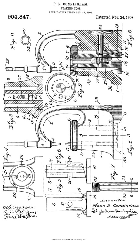
In the accompanying drawing, wherein an embodiment of the invention is shown, Fig. 1 is a side elevation of a staking tool to which the improved friction jewel setting device has been attached, some of the parts being shown in section; Pig; 2 is a plan view of the same; Fig. 3 is a vertical sectional view through the friction jewelsetting device; and Fig. 4 is a plan view of the frame of the setting device.
In Figs. 1 and 2 of the drawing is shown a staking tool of the kind well known in the watchmaking and watch-repairing industry. The tool is provided with a base 1 from which projects an integrally-formed goose-neck 2, the free end of which terminates in a tool guide or boss 3 having a vertically disposed guide opening through which various tools, such as punches, reamers and the like are extended to perform operations on watch parts supported on an adjustable plate or anvil member 4, said plate being apertured at 25 to accommodate punches and the like of various size and being fixed in the desired position of adjustment by means of a set screw, the knurled head 5 of which is exposed at the back of the base 1 of the staking tool. The parts thus far described form part of a staking tool of well known construction and are not a part of the invention.
The supporting frame for the improved friction jewel-setting device is preferably composed of the two parts 6 and 7, shown in separated position in Fig. 4. The main frame portion 6 is formed with a recess 8 shaped to fit the reduced portion 9 on boss 3, and the member 7 has a similar recess 10 which embraces the opposite side of portion 9 of the goose-neck. The main frame member 6 is cut out as indicated at. 11, and the member 7 fits within this cut-out portion.
The two frame elements 6 and 7, when placed together, with member 7 located in cut-out portion 11 of the main frame member 6, embrace or encircle the portion 9 located directly below the knurled nut 12 on boss 3. Frame members 6 and 7 thus clamp this portion 9 of boss 3 firmly between them, the screws 24 holding members 6 and 7 together. Frame member 6 is formed with an upwardly curved forward end portion 13 terminating in a clevis 14 between the sides of which is located the fixed pin 15. The clevis and pin 15 are intended for the pivotal reception of an operating arm or lever 16, having an open hook-shaped end 17 which detachably engages about the pin 15 in the manner shown in Fig. 1.
When in its operative position, the lever or arm 16 has its hooked end 17 engaged around the pin 15 and the body of the arm extends rearwardly and overlies the guide opening extending through the boss 3 of the staking tool. Thus, any tool, such as a punch indicated at 18, jewel pusher member or the like, extending through the guide opening in boss 3, will be in position to be thrust downwardly by arm 16 to operate upon a watch plate or other watch element 19 located upon the plate 4. To regulate the extent of downward movement of the lever or arm 16 and thereby govern the extent of descent of the tool depressed downwardly through boss 3 thereby, a stop member 21 is provided, said member being in the form of a knurled nut adjustable up or down upon the threaded rod or post 22 extending vertically from the top of the frame member 6 near the rear end 23 thereof.
In operation, a watch plate or other watch part intended for the reception of the jewels, is placed upon plate 4 or perhaps on a so-called “stump” held upon or substituted for the plate. With handle 16 either swung outwardly, as shown in Fig. 2 or else detached from the end of the frame member 6 to be out of the way, a reamer is inserted through guide opening in boss 3 and the hole in the watch plate reamed out to the proper size for the friction-fit reception of the jewel. The extent of descent of a pusher member to force the jewel in place in its opening is next determined, and the stop member 21 is adjusted accordingly. A pusher member is then placed in the guide opening in boss 3, the handle or lever 16 is hooked around pin 15 and then is manually pressed down until its descent is stopped by the stop member 21, when it will be found that the pusher member has forced the jewel into position in the opening in the watch plate.
When the jewel setting device is not in use, the handle 16 can either be swung out of the way of boss 3 or can be easily detached from its engagement with pin 15 thereby leaving the upper end of boss 3 unimpeded and permitting the tool to be used in every capacity to which a staking tool is adapted. To use the device as a jewel removal and setting tool, the placement of the operating handle in position is speedily done. By removal of the screws 24, the frame, composed of the co-operating members 6 and 7, carrying all parts of the jewel-setting device is removable as a unit, leaving the staking machine in its normal, original state. Thus, the fitment of the jewel removal and setting device to a staking machine in no manner damages or defaces the machine, as no holes need be drilled or other elements employed likely to damage the machine, decrease its value or minimize its various functions.
While the drawing shows a staking tool of a certain well-known make, it will be understood that the improved jewel-setting device can readily be applied to almost any staking tool as most of these machines are generally similar in construction and used for the same purposes.
What I claim is:—
1. A device of the character described comprising a staking tool having a goose-neck terminating in a tool guide, a frame having means for securing it upon the end of said goose-neck above the guide, an operating lever pivoted on the frame laterally of the goose-neck and capable of pivotal movement to extend across the upper end of the tool-guide, and adjustable means carried by said frame above the goose-neck for regulating the extent of descent of the lever.
2. A device of the character described comprising a staking tool having a goose-neck terminating in a tool guide, a frame provided with a clamp portion embracing said guide at the upper end thereof, said frame provided with an upwardly curved front end extending laterally of the goose-neck, a lever having its end pivotally mounted in the front end of the frame, said lever normally overlying the upper end of the tool guide, and an adjustable stop member at the opposite end of the frame, said stop member acting to regulate the extent of pivotal descent of the lever.
3. A device of the character described comprising, a frame member having a lever pivoted at one of its ends and a regulatable stop member for said lever located at its opposite end, and a clamping portion on the frame member located between the pivotal point of said lever and the stop member for attachment of the frame to the end of the goose-neck of a staking machine.
4. A friction jewel removing and setting device for staking tools, comprising, a two-part frame adapted to embrace the end of a staking tool goose-neck and clamp the same, one of the frame parts having an upwardly extended devised end, the opposite end of said frame part having a vertically movable adjustable nut, a pivoted lever having one of its ends mounted in the devised end of the frame part, said lever extending across the frame and the adjustable nut and having its position of descent governed by the position of said nut, the end of the lever located in the devised portion of the frame being formed with an open hook whereby it may be readily detached from the clevis.
5. A device of the character described comprising, a frame member having a lever pivotally attached at one of its ends, an upwardly extending threaded post at its other end, an adjustable stop member mounted for vertical adjustment on said post, and a clamp located intermediate of the post and pivotal point of the lever and by which the frame and parts carried thereby may be detachably secured to the goose-neck of a staking tool.
6. A device of the character described comprising, a frame member having a forward, upturned end, a lever pivotally mounted in said end, an adjustable stop near the other end of the frame mounted for vertical adjustment to limit the descent of the lever, and means for detachably securing the frame to the goose-neck of a staking tool so that a tool located in the guide opening of said staking tool will be contacted by the lever at a point between the pivot point of the lever and the adjustable stop.
7. A device of the character described comprising a staking tool having a substantially vertical frame portion formed with a tool guide, a friction jewel removing and setting device having a substantially horizontal frame removably mounted upon the vertical frame portion of the staking tool, an operating lever pivoted on one end of said last named frame laterally of the vertical frame portion of the staking tool and capable of pivotal movement to extend across the upper end of the tool guide, and adjustable means for limiting the descent of the lever toward the tool guide.
EDWARD RENZ.
