UNITED STATES PATENT OFFICE
LESTER J. WILLIAMS, OF LEBANON, NEW HAMPSHIRE, ASSIGNOR TO FRANK B. KENDRICK AND WILLIAM F. DAVIS, OF LEBANON, NEW HAMPSHIRE, PARTNERS TRADING AS THE FIRM OF KENDRICK & DAVIS.
WATCHMAKER’S STAKING-TOOL.
SPECIFICATION forming part of Letters Patent No. 707,887, dated August 26, 1902.
Application filed May 10, 1902. Serial No. 106,748. (No model.)
To all whom it may concern:
Be it known that I, Lester J. Williams, a citizen of the United States, residing at Lebanon, in the county of Grafton and State of New Hampshire, have invented certain new and useful Improvements in Watchmakers’ Staking-Tools, of which the following is a specification, reference being had therein to the accompanying drawings, which form a part of this specification.
My invention relates to improvements in watchmakers’ staking-tools, and has for its object the production of a tool of this character wherein the punch or plunger may be sustained within its guide in any desired position relative to the base to permit it to be withdrawn from and held free of the staff of the wheel without necessitating its complete withdrawal from the guide.
A further object is to provide a tool wherein the mechanism for setting the face-plate is capable of adjustment to facilitate the assembling of the tool, to compensate for wear through use on the various parts, or to accommodate this action to the requirements of the individual workman.
The invention consists in the novel features of construction hereinafter set forth and described, and more particularly pointed out in the claims hereto appended.
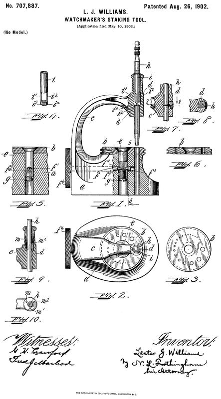
Referring to the accompanying drawings, Figure 1 is a side elevation, partly in section, of a staking-tool embodying the preferred form of my invention. Fig. 2 is a plan view thereof. Fig. 3 is a view of the bottom of the face-plate detached from the base. Fig. 4 is a view in perspective of the preferred form of the means for sustaining the punch or plunger. Fig. 5 is a section on the line 5 5 of Fig. 1. Fig. 6 is a sectional view of the face-plate detached from the base. Fig. 7 is a view showing a modified form of the means for sustaining the punch or plunger. Fig. 8 is a section on the line 8 8 of Fig. 7. Fig. 9 is a view showing a still further modified form of said means, and Fig. 10 is a plan view of the modification shown in Fig. 9.
Like letters refer to like parts throughout the several views.
In the accompanying drawings, a indicates the base of the staking-tool, which is provided with the usual openings to permit the mounting thereon of the face-plate b and the escape of the expelled staff. This base-plate also carries the arm or gooseneck c, which has formed thereon the guide-sleeve d, the opening in which is in alinement with the said escape-opening. The face-plate b is provided with a central opening presenting a beveled surface to increase the area of frictional contact and insure a more perfect centering of the said plate, a vertical bearing-face, and a series of graduated openings equidistant from a common center to accommodate a punch or plunger or other tool of different diameters, said plate being rotatable to permit said openings, respectively, to be brought into alinement with said escape-opening and said guide- sleeve. The face-plate b is maintained in the proper position relative to said base a by means of the pivot-pin e, provided with a conical head fitted to the opening in and flush with said plate. Extended through the lower part of this pin is an opening adapted to receive a shaft f, having in its length a reduced eccentric or cam portion f', acting in said opening, by means of which the pin e is drawn downward or forced upward to bind said faceplate against or release it from engagement with the base a to set it or permit it to be rotated, respectively. This shaft f is seated in a bearing formed in the base a, said bearing being on both sides of the opening for said pivot-pin e. The reduced eccentric or cam portion f' forms shoulders adapted to bear upon reverse sides of the pivot-pin e to hold it in position. This shaft extends without said base, and its exposed end is equipped with a knurled head by which it is manipulated. The various parts are all finished and must be finely adjusted, as the device must act with the greatest accuracy. To facilitate such adjustment, I provide a compensating-screw g, acting in the lower portion of the pivot-pin and against the eccentric or cam f', by means of which the throw of said cam may be regulated so as to overcome any slight irregularities in finish in assembling, wear from extensive use, or to suit the individual workman. Acting in the guide-sleeve d is a punch or plunger h, by means of which the staff is expelled from the wheel. The guide-sleeve d is so arranged that said plunger may be sustained therein in any desired position relative to the faceplate, so as to be capable of being lifted free from the work to enable the temporary use of other tools without requiring the complete removal of the said plunger or punch.
In the preferred form of my invention, as shown in Figs. 1, 2, and 4, I enlarge the upper portion of the guide-sleeve d and countersink therein a sleeve i, provided with a plurality of spring-tongues i' i2, carrying, respectively, a semicircular bearing-face, as i3 i4, adapted to partially encompass and frictionally engage the punch or plunger h. This sleeve i may be secured within the guide- sleeve d in any desired manner; but preferably it is made a “ driving fit.”
In the modification shown in Figs. 7 and 8 I dispense with the sleeve i and merely employ a plurality of spring-tongues, as j j', seated within the guide-sleeve d and partially encompassing the punch or plunger. These tongues are inserted through openings made in the guide-sleeve and are secured in this relation by means of a screw-plug k, bearing against their outer ends.
In the modification shown in Figs. 9 and 10 I provide a plurality of spring-tongues m m' m2 which extend obliquely downward from the top of the guide-sleeve d, penetrating a chamber therein which is provided to permit a slight lateral movement of the lower ends of said springs. These tongues are secured in position in any desired manner; but preferably holes are drilled, and said tongues are driven therein, being a tight fit.
The operation of my staking-tool in so far as has not already been disclosed is as follows: The staff of the balance or other wheel having been fitted in the proper opening in the face-plate b, the clamping mechanism is released by means of the knurled head f4, which rotates the shaft f and the eccentric or cam portion thereof. This forces the pivot- pin e upward until it is freed from engagement with the face-plate b. The said plate is then rotated until the proper opening is in alinement with the escape-opening in the base and with the plunger-guide sleeve. When it is properly centered, it is set in this position by reversing the action of the cam. If it is found that the throw of the cam is insufficient to properly release or clamp said plate or that there is a tendency to give too much motion to these parts to accomplish the desired result, this may be remedied by resetting the screw g. A smooth action of this mechanism is assured by reason of the double bearing for the shaft f and the shoulders f2 and f3, which are always in engagement with the pivot-pin e on reverse sides thereof, owing to the reduced diameter of the cam portion f'.
The operation of the sustaining spring- tongues is substantially identical in the preferred form of my invention and in each of the modifications herein shown and described.
As the punch or plunger is inserted in the guide-sleeve d its end will spread the spring- tongues, causing them to engage the sides thereof. This engagement will be sufficient to sustain the weight of the punch or plunger, but will not interfere to any extent with its reciprocation while in use. If it be desired to examine the work in hand, to employ other tools upon it before the complete expulsion of the staff, or to temporarily cease this operation for any other reason or purpose, it is merely necessary to raise the punch or plunger to the necessary height, and the spring-tongues will hold it in this position until it is desired to resume its use. This not only facilitates the work in hand, but obviates the necessity of a repeated refitting of the plunger to the guide- sleeve and the resulting annoyance.
It is not my intention to limit my invention to the precise construction herein shown and described, as it is apparent that there may be many deviations therefrom without departing from the spirit of my invention.
Having described the invention, what I claim as new, and desire to have protected by Letters Patent, is--
1. In a staking-tool, in combination a perforated base, a punch or plunger, a guide therefor, and means adapted to frictionally engage said punch or plunger whereby said punch or plunger may be sustained in said guide in any desired position relative to said base.
2. In a staking-tool, in combination a perforated base, a punch or plunger, a guide therefor, and means comprising a plurality of spring-tongues adapted to engage said punch or plunger whereby it may be sustained in said guide in any desired position relative to said base.
3. In a staking-tool, in combination a perforated base, a punch or plunger, a guide therefor, a means comprising a sleeve countersunk in said guide and a plurality of spring-tongues carried thereby and adapted to engage said punch or plunger whereby it may be sustained in said guide in any desired position relative to said base.
4. In a staking-tool, in combination a perforated base, a punch or plunger, a guide therefor, and means comprising a sleeve countersunk in said guide a plurality of spring- tongues carried thereby and bearing-surfaces carried by said tongues and adapted to engage said punch or plunger whereby it may be sustained in any desired position relative to said base.
5. In a staking-tool, in combination, a perforated base, a punch or plunger, a rotatable face-plate carried by said base, a pivot-pin connecting said base and said plate, a cam whereby said pivot-pin is reciprocated to release or clamp said face-plate and means comprising an adjustable contact carried by said pivot-pin and acting against said cam whereby the throw of said pivot-pin by said cam may be regulated.
6. In a staking-tool, in combination, a perforated base, a punch or plunger, a rotatable face-plate carried by said base, a pivot-pin connecting said base and said plate, a cam whereby said pivot-pin is reciprocated to release or clamp said face-plate and a set-screw carried by said pivot-pin.
. In a staking-tool, in combination a perforated base, a punch or plunger, a rotatable face-plate carried by said base, a pivot-pin connecting said base and said face-plate having an opening extending therethrough, a shaft seated in said base and extending through said opening a portion of said shaft being reduced and eccentric, said portion being within the opening in said pivot-pin, whereby shoulders are formed to bear upon the reverse sides of said pivot-pin, and said face-plate may be released from or clamped against said base.
In witness whereof I have hereunto set my hand, this 29th day of April, 1902, in the presence of two witnesses.
LESTER J. WILLIAMS.
Witnesses:
M. D. COBLEIGH,
N. M. BAKER.
Be it known that I, Lester J. Williams, a citizen of the United States, residing at Lebanon, in the county of Grafton and State of New Hampshire, have invented certain new and useful Improvements in Watchmakers’ Staking-Tools, of which the following is a specification, reference being had therein to the accompanying drawings, which form a part of this specification.
My invention relates to improvements in watchmakers’ staking-tools, and has for its object the production of a tool of this character wherein the punch or plunger may be sustained within its guide in any desired position relative to the base to permit it to be withdrawn from and held free of the staff of the wheel without necessitating its complete withdrawal from the guide.
A further object is to provide a tool wherein the mechanism for setting the face-plate is capable of adjustment to facilitate the assembling of the tool, to compensate for wear through use on the various parts, or to accommodate this action to the requirements of the individual workman.
The invention consists in the novel features of construction hereinafter set forth and described, and more particularly pointed out in the claims hereto appended.
Referring to the accompanying drawings, Figure 1 is a side elevation, partly in section, of a staking-tool embodying the preferred form of my invention. Fig. 2 is a plan view thereof. Fig. 3 is a view of the bottom of the face-plate detached from the base. Fig. 4 is a view in perspective of the preferred form of the means for sustaining the punch or plunger. Fig. 5 is a section on the line 5 5 of Fig. 1. Fig. 6 is a sectional view of the face-plate detached from the base. Fig. 7 is a view showing a modified form of the means for sustaining the punch or plunger. Fig. 8 is a section on the line 8 8 of Fig. 7. Fig. 9 is a view showing a still further modified form of said means, and Fig. 10 is a plan view of the modification shown in Fig. 9.
Like letters refer to like parts throughout the several views.
In the accompanying drawings, a indicates the base of the staking-tool, which is provided with the usual openings to permit the mounting thereon of the face-plate b and the escape of the expelled staff. This base-plate also carries the arm or gooseneck c, which has formed thereon the guide-sleeve d, the opening in which is in alinement with the said escape-opening. The face-plate b is provided with a central opening presenting a beveled surface to increase the area of frictional contact and insure a more perfect centering of the said plate, a vertical bearing-face, and a series of graduated openings equidistant from a common center to accommodate a punch or plunger or other tool of different diameters, said plate being rotatable to permit said openings, respectively, to be brought into alinement with said escape-opening and said guide- sleeve. The face-plate b is maintained in the proper position relative to said base a by means of the pivot-pin e, provided with a conical head fitted to the opening in and flush with said plate. Extended through the lower part of this pin is an opening adapted to receive a shaft f, having in its length a reduced eccentric or cam portion f', acting in said opening, by means of which the pin e is drawn downward or forced upward to bind said faceplate against or release it from engagement with the base a to set it or permit it to be rotated, respectively. This shaft f is seated in a bearing formed in the base a, said bearing being on both sides of the opening for said pivot-pin e. The reduced eccentric or cam portion f' forms shoulders adapted to bear upon reverse sides of the pivot-pin e to hold it in position. This shaft extends without said base, and its exposed end is equipped with a knurled head by which it is manipulated. The various parts are all finished and must be finely adjusted, as the device must act with the greatest accuracy. To facilitate such adjustment, I provide a compensating-screw g, acting in the lower portion of the pivot-pin and against the eccentric or cam f', by means of which the throw of said cam may be regulated so as to overcome any slight irregularities in finish in assembling, wear from extensive use, or to suit the individual workman. Acting in the guide-sleeve d is a punch or plunger h, by means of which the staff is expelled from the wheel. The guide-sleeve d is so arranged that said plunger may be sustained therein in any desired position relative to the faceplate, so as to be capable of being lifted free from the work to enable the temporary use of other tools without requiring the complete removal of the said plunger or punch.
In the preferred form of my invention, as shown in Figs. 1, 2, and 4, I enlarge the upper portion of the guide-sleeve d and countersink therein a sleeve i, provided with a plurality of spring-tongues i' i2, carrying, respectively, a semicircular bearing-face, as i3 i4, adapted to partially encompass and frictionally engage the punch or plunger h. This sleeve i may be secured within the guide- sleeve d in any desired manner; but preferably it is made a “ driving fit.”
In the modification shown in Figs. 7 and 8 I dispense with the sleeve i and merely employ a plurality of spring-tongues, as j j', seated within the guide-sleeve d and partially encompassing the punch or plunger. These tongues are inserted through openings made in the guide-sleeve and are secured in this relation by means of a screw-plug k, bearing against their outer ends.
In the modification shown in Figs. 9 and 10 I provide a plurality of spring-tongues m m' m2 which extend obliquely downward from the top of the guide-sleeve d, penetrating a chamber therein which is provided to permit a slight lateral movement of the lower ends of said springs. These tongues are secured in position in any desired manner; but preferably holes are drilled, and said tongues are driven therein, being a tight fit.
The operation of my staking-tool in so far as has not already been disclosed is as follows: The staff of the balance or other wheel having been fitted in the proper opening in the face-plate b, the clamping mechanism is released by means of the knurled head f4, which rotates the shaft f and the eccentric or cam portion thereof. This forces the pivot- pin e upward until it is freed from engagement with the face-plate b. The said plate is then rotated until the proper opening is in alinement with the escape-opening in the base and with the plunger-guide sleeve. When it is properly centered, it is set in this position by reversing the action of the cam. If it is found that the throw of the cam is insufficient to properly release or clamp said plate or that there is a tendency to give too much motion to these parts to accomplish the desired result, this may be remedied by resetting the screw g. A smooth action of this mechanism is assured by reason of the double bearing for the shaft f and the shoulders f2 and f3, which are always in engagement with the pivot-pin e on reverse sides thereof, owing to the reduced diameter of the cam portion f'.
The operation of the sustaining spring- tongues is substantially identical in the preferred form of my invention and in each of the modifications herein shown and described.
As the punch or plunger is inserted in the guide-sleeve d its end will spread the spring- tongues, causing them to engage the sides thereof. This engagement will be sufficient to sustain the weight of the punch or plunger, but will not interfere to any extent with its reciprocation while in use. If it be desired to examine the work in hand, to employ other tools upon it before the complete expulsion of the staff, or to temporarily cease this operation for any other reason or purpose, it is merely necessary to raise the punch or plunger to the necessary height, and the spring-tongues will hold it in this position until it is desired to resume its use. This not only facilitates the work in hand, but obviates the necessity of a repeated refitting of the plunger to the guide- sleeve and the resulting annoyance.
It is not my intention to limit my invention to the precise construction herein shown and described, as it is apparent that there may be many deviations therefrom without departing from the spirit of my invention.
Having described the invention, what I claim as new, and desire to have protected by Letters Patent, is--
1. In a staking-tool, in combination a perforated base, a punch or plunger, a guide therefor, and means adapted to frictionally engage said punch or plunger whereby said punch or plunger may be sustained in said guide in any desired position relative to said base.
2. In a staking-tool, in combination a perforated base, a punch or plunger, a guide therefor, and means comprising a plurality of spring-tongues adapted to engage said punch or plunger whereby it may be sustained in said guide in any desired position relative to said base.
3. In a staking-tool, in combination a perforated base, a punch or plunger, a guide therefor, a means comprising a sleeve countersunk in said guide and a plurality of spring-tongues carried thereby and adapted to engage said punch or plunger whereby it may be sustained in said guide in any desired position relative to said base.
4. In a staking-tool, in combination a perforated base, a punch or plunger, a guide therefor, and means comprising a sleeve countersunk in said guide a plurality of spring- tongues carried thereby and bearing-surfaces carried by said tongues and adapted to engage said punch or plunger whereby it may be sustained in any desired position relative to said base.
5. In a staking-tool, in combination, a perforated base, a punch or plunger, a rotatable face-plate carried by said base, a pivot-pin connecting said base and said plate, a cam whereby said pivot-pin is reciprocated to release or clamp said face-plate and means comprising an adjustable contact carried by said pivot-pin and acting against said cam whereby the throw of said pivot-pin by said cam may be regulated.
6. In a staking-tool, in combination, a perforated base, a punch or plunger, a rotatable face-plate carried by said base, a pivot-pin connecting said base and said plate, a cam whereby said pivot-pin is reciprocated to release or clamp said face-plate and a set-screw carried by said pivot-pin.
. In a staking-tool, in combination a perforated base, a punch or plunger, a rotatable face-plate carried by said base, a pivot-pin connecting said base and said face-plate having an opening extending therethrough, a shaft seated in said base and extending through said opening a portion of said shaft being reduced and eccentric, said portion being within the opening in said pivot-pin, whereby shoulders are formed to bear upon the reverse sides of said pivot-pin, and said face-plate may be released from or clamped against said base.
In witness whereof I have hereunto set my hand, this 29th day of April, 1902, in the presence of two witnesses.
LESTER J. WILLIAMS.
Witnesses:
M. D. COBLEIGH,
N. M. BAKER.
